|
|
International Journal of Arrhythmia 2011;12(4): 10-15.
|

Background
The Implantable Cardioverter Defibrillator (ICD)
is an implantable medical device that is used to
treat ventricular tachycardia and fibrillation with
high voltage therapy. It has the capability to deliver
low voltage pacing therapy as well. The device has a
basic onboard micro-computer that serves as the
overall controller of all diagnostic and therapeutic
functions, a high voltage charging section, a high
voltage output section, and a connector top header
that connects the device to the cardiac leads.
While the basic conceptual work on a fully
automatic implantable defibrillator began in the
1950s, the practical embodiment of the device only
began to take shape in 1971 with the work of Michel
Mirowski and Morton Mower. After overcoming the
skeptics, Mirowski and Mower demonstrated a
prototype in a canine subject in 1979. This led to
efforts to develop the device in the early 1980s by
Intec Systems, which produced the AID™, and then
by Cardiac Pacemakers Inc., which produced the
Ventak®.1 These early devices were fully automatic
and implantable and had a displacement volume in
the range of 150 to 200 cubic centimeters (cc). Other
companies then began product development efforts
that led to widespread commercialization of the ICD
in the early 1990s.
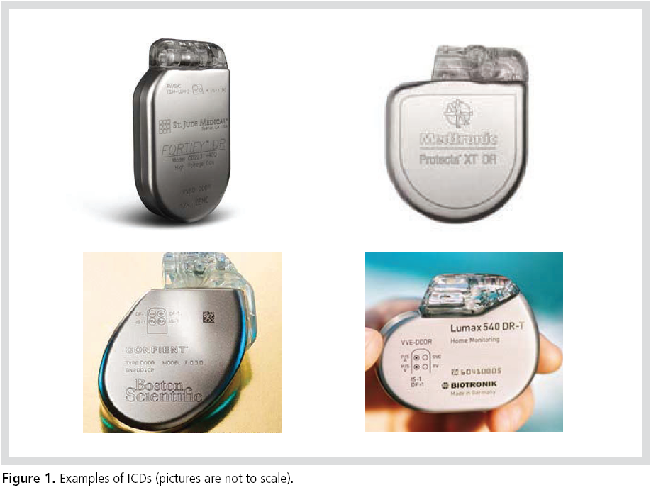
Technology Status
In devices that have Cardiac Resynchronization
Therapy (CRT) capability, devices that represent
the current state of the art in ICD technology have
an overall displacement volume in the range of
slightly less than 30 cc to over 40 cc. Various
physiological shapes are available to the designer to
minimize the pectoral pocket size, shape, and
bulge. The incision length for the insertion of the
device into the pocket can also be minimized. The
device shape is chosen to maximize the patient’s
comfort and to minimize pocket erosion over time
(Figure 1).
The devices are packaged in a biocompatible
enclosure that is formed from commercially
available pure Titanium sheet stock. A laser
welding process is used to seam-weld the
enclosure, which ensures that the components
packaged within it are hermetically sealed from
body fluids. A thermoplastic or thermoset epoxy
resin is used to form the connector top header,
which serves as a fixture for connection to the
endocardial leads.
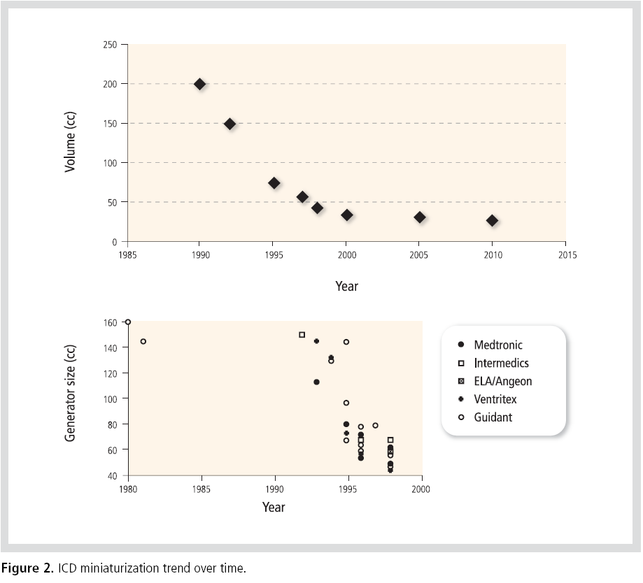
The miniaturization of ICDs took place quite
rapidly in the 1990s. Significant technological
developments in commercial electronics facilitated
the miniaturization of ICD electronic packaging.
The ability to configure the unique larger
components into custom shapes that fit within the
device also helped to dramatically decrease its
overall volume. Currently manufactured ICDs
appear to be converging on an asymptote volume of
25 cc(Figure 2).2
Why is an ICD bigger and more expensive than a pacemaker?
The components and circuits within an ICD are
designed and shaped to fit quite efficiently within
the device to minimize wasted space and to conform
to the overall profile of the device enclosure. Very
dense electronics packaging techniques, a dense
circuit-to-circuit interconnect, and high
performance materials are employed to minimize
the size and maximize the device’s reliability.
However, the ICD has a number of unique
components that add to its overall size and
dramatically increase its cost of manufacture. A
special Lithium Sliver Vanadium Oxide (LI SVO)
battery is used as the charging supply for its high
voltage therapy function. This type of battery
typically adds approximately 3 cc of volume as
compared to a conventional pacemaker battery. A
special Aluminum Electrolytic capacitor set is
charged in order to serve as the high voltage energy
reservoir for defibrillation therapy. This capacitor
set, which is not present in a conventional
pacemaker, adds approximately 8 cc of volume to
the device. A special DC-to-DC converter takes the
low-voltage high-current input from the battery
and converts it to a high-voltage low-current
source that charges the high voltage capacitor set.
This DC-to-DC Converter is also not present in a
conventional pacemaker, and it adds approximately 2 cc of volume to the device (Figure 3).
The most critical section of the ICD is the high
voltage output circuit(Figure 4). It controls the
delivery of defibrillation therapy to the patient. The
actual flow of current is typically controlled by 4
large Insulated Gate Bipolar Transistors (IGBT).
Because these transistors switch instantaneous
voltages that can be as high as 900 V, they must be
sized in accordance with high voltage standoff
design rules that prevent arcing and shorting
within the transistor during the switching
operation. In addition, each of the transistors must
be placed at a specific spacing from the other to
prevent arcing and shorting between transistors.
These (4) transistors are not present in a
conventional pacemaker, and together, they add
approximately 5 cc of volume to the device. In
addition, these special transistors, along with their
special electronics packaging, add a significant cost
to the device (Figure 4).


Future Generations of the ICD
The current state of the art in ICD packaging has
reached technological maturity. Increased miniaturization
will probably yield just a marginal decrease in the
overall displacement volume of the device, which
will be accompanied by a significant increase in
manufacturing cost. The cost of the precious metals
used in the device continues to rise. Because the
ICD has a number of components that are unique to
its application, it is doubtful that the current
advances being made in the high volume personal
electronics revolution would be of use in reducing
its size and cost.
If the clinical requirements for an ICD could be
modified or relaxed, it would be possible to conceive
of a new generation of devices that are smaller and
that cost less. Relaxation of the design constraints
could lead to the modification or complete
elimination of the components within the ICD.
Special batteries, high voltage capacitors, and high
voltage output circuits could become smaller and
less costly to manufacture.
The first example of a future generation ICD is one that allows for a significant increase in its
charge time in preparation for the delivery of
therapy to the patient. The device would charge at
a lower input power. A reduction in the maximum
target charging voltage would make possible a
significant reduction in the size of the device
circuits and their respective components. In this
case, alternative battery chemistries could be
employed, such as Carbon Monofluoride (CFx). The
size of the battery, the high voltage capacitor set,
and the high voltage output circuit could also be
reduced, bringing about a significant cost reduction
as well. It is recognized that this new ICD may not
be suitable for all patients.
The second example of a future generation ICD is
one that is more disruptive and unconventional in
its design approach. This device is able to sense and
detect tachyarrhythmias just before their onset.
One class of therapy regime would consist of low
voltage pace trains that would decelerate the
arrhythmia into a normal sinus rhythm.2 Another
class of therapy regime would stimulate the
autonomic nervous system via thoracic spinal cord
stimulation in a way that would prevent the onset
of an arrhythmia.4 This new generation of devices
has the function of a low voltage implantable pulse
generator, and it looks more like a pacemaker or a
spinal cord stimulator. It would make possible a
significant size and cost reduction relative to the
design of the conventional ICD.
Summary
The current state of the art in ICD technology has
reached its maturity. The ICD has a number of
components and circuits that are unique to its
application, and a significant size and cost
reduction of the conventional ICD is unlikely.
Changes in the clinical requirements of the ICD
could lead to the development of a future
generation of devices that would be much smaller
and less costly to manufacture.
Figure 4. High voltage output section demonstrating the generous spacing required between four large Insulated Gate
Bipolar Transistors (IGBT) to prevent arcing and shorting between components.
Employee : MS. Fayram is a board member of
Clinical Advisory Group of St. Jude Medical
International.
References
- Hauser RG. Development and industrialization of the Implantable Cardioverter-Defibrillator :A personal and historical perspective.
Card Electrophysiol Clin.
2009;1:117-127.
- Gottlieb CD, Callans DL. New Devices: Functions and Features.
Cardiac Electrophysiology Review
1998;2:272-276.
- Efimov IR, Kroll MW, Tchou PJ. Cardiac Bioelectric Therapy: Mechanisms and Practical Implications.
Springer Science & Business Media. 2009:382-383.
- Lopshire JC, Zhou X, Dusa C, Ueyama T, Rosenberger J, Courtney N, Ujhelyi M, Mullen T, Das M, Zipes DP. Spinal cord stimulation improves ventricular function and reduces ventricular arrhythmias in a canine postinfarction heart failure model.
Circulation.
2009;120: 286-294.
|
|
|
|